How to Draw a Circle in Isometric Projection
The isometric projection of an object on a vertical plane of projection by placing the object in such a fashion that its three perpendicular edges make equal inclinations with the plane of projection.
Isometric Project
Since the three perpendicular edges of an object are projected in the isometric project at equal axonometric angles, the angles betwixt those edges in the isometric projection will be at 120º. The lengths of the 3 perpendicular edges of an object in the isometric project are foreshortened in the same proportion.
To understand the principles of isometric projection and to know the extent to which the edges are foreshortened.
A cube is placed with 3 of its perpendicular edges making equal inclinations with the vertical aeroplane of projection and is projected on information technology. As shown in figure a.
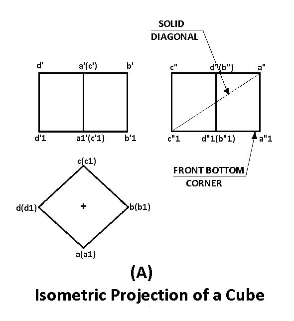
The projections of a cube when placed on HP such that two of its square faces making equal inclinations with the plane of projection.
Next, tilt the cube towards the observer such that information technology rests on the front bottom corner with the solid diagonal opposite to the corner in which information technology rests and passing through the acme front end corner, is perpendicular to the plane of projection.
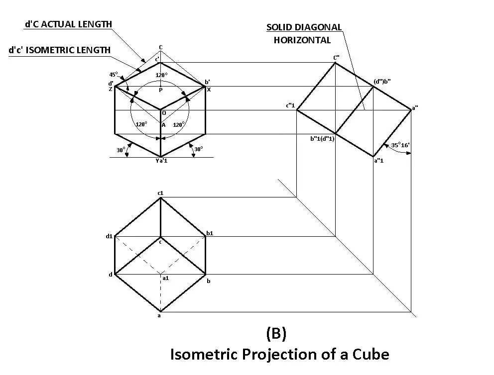
The Figure-B illustrates this position of the cube. Every bit seen in the left view, the solid diagonal a "c1" is perpendicular to the plane of projection. In this position, the front end and top views are projected. The three perpendicular edges AB, AD & AA1 volition be equally inclined at an angle of 35° 16′ to the airplane of projection.
But the projection of these edges, i.e., a'b', a'd' & a'a1′ are at an bending of 120º to each other and likewise they are foreshortened to the aforementioned length. The front end view of the cube, therefore, represents its isometric projection.
Read also: Dimensions and Types of Dimensioning Systems
To Find The Length of The Edges in The Isometric Projection:
To find the extent to which the lengths of the edges are foreshortened.
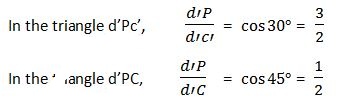
Depict a square d'Ab'C od sides equal to the actual length of the edges of the cube with d'b' equally the mutual diagonal. d'C is the actual length of the edge, whereas respective border d'c' in the isometric projection is foreshortened. This foreshortened length is known as isometric length of the border of the cube.
d'C is the actual length of the border, whereas corresponding edge d'c' in the isometric projection is foreshortened. This foreshortened length is known as the isometric length of the edge of the cube.
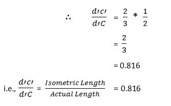
i.due east., Isometric Length = 0.816 Actual Length. Thus in the isometric projection, the actual lengths of the objects are reduced in the ratio of 2:iii. Or the isometric length is 0.816 of the actual length.
When an isometric project is to be fatigued, all the edges of the object parallel to the 3 isometric axes, take to be reduced to their corresponding isometric lengths which will exist equal to 0.816 times their actual length.
Isometric Scale
In isometric projection, all edges of the object along the direction of three isometric axes are foreshortened to 0.816 times their exact lengths. To facilitate the easy and quick method of measurement of lengths of the diverse edges in their reduced sizes while cartoon the isometric projection of the object, a special scale known as the isometric scale is constructed.

On this scale, the isometric lengths respective to the given actual lengths can be obtained directly. The isometric calibration is constructed as follows:
Describe a horizontal line OA. THrough O draw OP and OQ at 30º & 45º to the horizontal respectively. On OQ mark the actual scale in mm. Draw verticals from each of the division points on the actual calibration to cut OP at the corresponding divisions. The sectionalisation points obtained on OP, called isometric scale, mensurate the distances reduced to isometric lengths.
Isometric View or Isometric Drawing
To draw the isometric projection of an object, every dimension of the object along the isometric axes, accept to be reduced to the isometric scales.
This has ii disadvantages:
- First, it is time-consuming and
- Information technology is on such a drawing when required the distances betwixt any two points along the isometric axes cannot exist measured directly with the actual scale.
To overcome these difficulties, an object tin can be quickly represented in the isometric class using the actual calibration instead of the isometric scale. Such a view will be precisely is of the same shape but larger than that fatigued to the isometric scale.

The Effigy-A shows a cube of 20mm sides drawn to the isometric scale.
The Figure-B shows the cube of the aforementioned dimensions drawn to the bodily scale.
The view drawn to the exact scale is known as the Isometric View (Isometric Cartoon). While that fatigued using the isometric scale is known as as the Isometric Projection.
Isometric & Not-Isometric Lines
In the figure, the 3 perpendicular edges of the cube OX, OY, & OZ are foreshortened equally and are at equal inclinations of 120º to each other and are known as isometric axes. The lines drawn parallel to the isometric axes are known as Isometric Line.

Any other line which is not parallel to any of the isometric axes is known as Non-Isometric Line. The lines XY, YZ & ZX are called non-isometric lines.
Since these lines are not parallel to the isometric axes, they are not foreshortened in the same proportion as the isometric lines. Too, those horizontal edges of the object which are non-isometric must not be fatigued at 30º. To draw the non-isometric lines, their ends should exist located and then joined. The surface XYZ is an oblique surface in isometric.
Dissimilar Positions of Isometric Representation
An object in isometric projection may be shown in eight different positions every bit shown in the Figure. Anyone item position may be selected so equally to illustrate all the important details of the object clearly.

However, the object will be drawn in isometric with its longest measurement either vertical or horizontal. The position in figure-B is known equally an isometric projection with axis reversed is drawn when the underneath surface of the object is to be shown.
That's information technology. Thanks for reading if yous have any questions well-nigh "Isometric Projection" ask in the comments I'll respond to you. Share this post if information technology's worth sharing.
If you lot like this article then please share information technology with your friends. And also you candownload the free PDF file of this article by clicking below.
Subscribe to the newsletter to go notifications of our new posts. Information technology's Free.
Yous might like to explore more in our weblog:
- 10 Dissimilar Types of Lines Used In Applied science Drawing
- Dimensions and Types of Dimensioning Systems
Source: https://www.theengineerspost.com/isometric-projection/
0 Response to "How to Draw a Circle in Isometric Projection"
Postar um comentário